

#
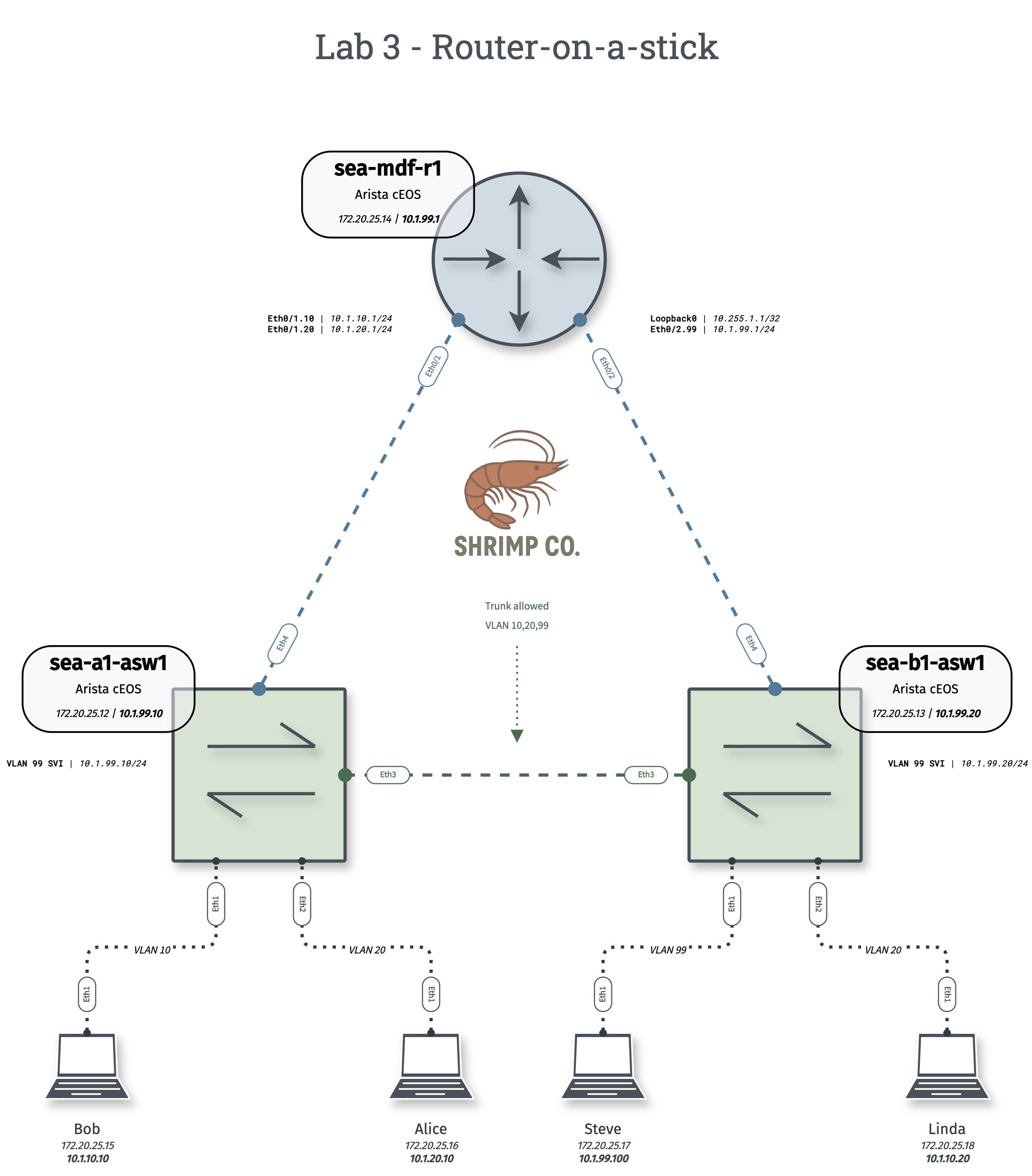
Lab 3 - Router-on-a-stick
Users are complaining they can't access servers in other departments. Deploy a router-on-a-stick solution to enable communication between VLANs
Tip: Individual topology files are available in the diagrams folder on my Github
#
Configuration Tasks
#
VLAN Configuration
Create and configure the following VLANs on both switches:
- VLAN 10 - Sales
- VLAN 20 - Engineering
- VLAN 99 - IT
#
Host & Access Port Configuration
#
Switchport Configuration
- Configure the inter-switch link (Eth3 on both switches) as trunk to carry only VLANs 10,20, and 99.
- Configure switch uplinks to router (Eth4 on both switches) as a trunk, allowing only necessary VLANs.
- Configure VLAN 99 SVI for sea-a1-asw1 - 10.1.99.10/24
- Configure VLAN 99 SVI for sea-b1-asw1 - 10.1.99.20/24
#
Router Configuration
- Configure gateways as subinterfaces for inter-VLAN routing:
- Eth1.10 with IP 10.1.10.1/24
- Eth1.20 with IP 10.1.20.1/24
- Eth2.99 with IP 10.1.99.1/24
- Configure Loopback0 with IP 10.255.1.1/32
Because Arista EOS uses the same code train for both switches and routers you need enabling routing globally with the command ip routing alongside specifying when a port is routed by issuing no switchport on the physical interface. This does not need to be done on the subinterface.
While traditionally "router-on-a-stick" refers to a single physical interface carrying multiple tagged VLANs, in this lab sea-mdf-r1 utilizes two physical interfaces (Eth1 and Eth2) in a "multi-stick" design. This choice was made for visual symmetry and doesn’t necessarily reflect best-practice network design.
#
Success Criteria
- Bob and Alice can ping each other (Inter-VLAN routing functioning)
- All hosts can ping their respective gateways
- Ping Loopback0 from Linda
- Run
tcpdump interface ethernet4 filter tcpon sea-b1-asw1 - Configure router with local user account other than admin, SSH to it from Steve.
- Look for the mac-addresses in the L2 header in your tcpdump and find on what interfaces the switch learned them. Then, on each device find a command that will output that interface's mac address to your terminal.
#
Verification Commands
# Show VLAN configuration
show vlan [brief]

# Show trunk interfaces and allowed VLANs
show interfaces trunk

# Show interface status and mode
show interfaces status

# Show MAC address table
show mac address-table [address] [dynamic]
# Show ARP table
show ip arp
# Show routing table
show ip route# Test reachability
ping X.X.X.X # (ping 10.1.20.1)
# Show network interface information
ifconfig
# Show default route/routing information
ip route show
#
Questions to Explore
- Why does router-on-a-stick use sub-interfaces instead of separate physical connections?
- What kind of routes are each subnet in the routing table?
- What happens to the VLAN tags when traffic reaches the router sub-interface?
- Why do hosts need default gateways configured now when they didn't before?
- What's the purpose of an ARP table? Where is it found?
- Imagine the scenario: Steve pings Loopback0 on sea-mdf-r1, when the router goes to send the return traffic how will the L2 & L3 headers look? What does the router use to build it?
"Host Access"
If SSH isn't working: docker exec -it <container-name> bash
Configure static IP: sudo ip addr add 10.1.10.10/24 dev eth1
Configure default route: sudo ip route add default via 10.1.20.1 dev eth1
Arista documentation isn't nearly as ubiquitous as Cisco's, nor can you find many beginner-friendly resources. In this case, there's no reference for Layer 3 subinterfaces in their user guide at all. The command-line syntax is extremely similar to Cisco though, so finding a guide for a Cisco configuration will get you most of the way there. I recommend Network Lessons